Saturday, December 31, 2022
10 i/p (1bit wide) ADDER:-
module add10 (cout3,cout2,cout1,s,a,b,c,d,e,f,g,h,i,j);
input a,b,c,d,e,f,g,h,i,j;
output cout3,cout2,cout1,s;
add9 ad1 (c3,c2,c1,s1,a,b,c,d,e,f,g,h,i);
ha h1 (c4,s,s1,j);
ha h2 (c5,cout1,c4,c1);
ha h3 (c6,cout2,c5,c2);
ha h4 (c7,cout3,c6,c3);
endmodule
TEST BENCH:-
module adtb ();
reg a,b,c,d,e,f,g,h,i,j;
wire cout3,cout2,cout1,s;
add10 dut (cout3,cout2,cout1,s,a,b,c,d,e,f,g,h,i,j);
integer z;
initial
begin
for (z=0;z<=1023;z=z+1)
begin
{a,b,c,d,e,f,g,h,i,j}= z;
#1;
$display(a,b,c,d,e,f,g,h,i,j,":",cout3,cout2,cout1,s);
end
end
endmodule
9 i/p ADDER (1bit wide) :-
module add9 (cout3,cout2,cout1,s,a,b,c,d,e,f,g,h,i);
input a,b,c,d,e,f,g,h,i;
output cout3,cout2,cout1,s;
add8 ad1 (c3,c2,c1,s1,a,b,c,d,e,f,g,h);
ha h1 (c4,s,s1,i);
ha h2 (c5,cout1,c4,c1);
ha h3 (c6,cout2,c5,c2);
ha h4 (c7,cout3,c6,c3);
endmodule
TEST BENCH :-
module adtb ();
reg a,b,c,d,e,f,g,h,i;
wire cout2,cout1,s;
add9 dut (cout3,cout2,cout1,s,a,b,c,d,e,f,g,h,i);
integer z;
initial
begin
for (z=0;z<=511;z=z+1)
begin
{a,b,c,d,e,f,g,h,i}= z;
#1;
$display(a,b,c,d,e,f,g,h,i,":",cout3,cout2,cout1,s);
end
end
endmodule
8 i/p (1bit wide) ADDER:-
module add8 (cout3,cout2,cout1,s,a,b,c,d,e,f,g,h);
input a,b,c,d,e,f,g,h;
output cout3,cout2,cout1,s;
add7 ad1 (c2,c1,s1,a,b,c,d,e,f,g);
ha h1 (c3,s,s1,h);
ha h2 (c4,cout1,c3,c1);
ha h3 (cout3,cout2,c4,c2);
endmodule
Testbench :-
module adtb ();
reg a,b,c,d,e,f,g,h;
wire cout2,cout1,s;
add8 dut (cout3,cout2,cout1,s,a,b,c,d,e,f,g,h);
integer j;
initial
begin
for (j=0;j<=255;j=j+1)
begin
{a,b,c,d,e,f,g,h}= j;
#1;
$display(a,b,c,d,e,f,g,h,":",cout3,cout2,cout1,s);
end
end
endmodule
7 i/p (1bit wide) ADDER:-
module add7 (cout2,cout1,s,a,b,c,d,e,f,g);
input a,b,c,d,e,f,g;
output cout2,cout1,s;
add6 ad1 (c2,c1,s1,a,b,c,d,e,f);
ha h1 (c3,s,s1,g);
ha h2 (c4,cout1,c3,c1);
ha h3 (c5,cout2,c4,c2);
endmodule
Testbench :-
module adtb ();
reg a,b,c,d,e,f,g;
wire cout2,cout1,s;
add7 dut (cout2,cout1,s,a,b,c,d,e,f,g);
integer j;
initial
begin
for (j=0;j<=127;j=j+1)
begin
{a,b,c,d,e,f,g}= j;
#1;
$display(a,b,c,d,e,f,g,":",cout2,cout1,s);
end
end
endmodule
6 i/p - 1bit wide ADDER:-
module add6 (cout2,cout1,s,a,b,c,d,e,f);
input a,b,c,d,e,f;
output cout2,cout1,s;
xlfa xl1 (c2,c1,s1,a,b,c,d,e);
ha h1 (c3,s,s1,f);
ha h2 (c4,cout1,c3,c1);
ha h3 (c5,cout2,c4,c2);
endmodule
Test Bench:-
module adtb ();
reg a,b,c,d,e,f;
wire cout2,cout1,s;
add6 dut (cout2,cout1,s,a,b,c,d,e,f);
integer j;
initial
begin
for (j=0;j<=63;j=j+1)
begin
{a,b,c,d,e,f}= j;
#1;
$display(a,b,c,d,e,f,":",cout2,cout1,s);
end
end
endmodule
Friday, December 30, 2022
XL-FA :- (5i/p -1bitwide adder):-
module xlfa(cout2,cout1,s,a,b,c,d,e);
input a,b,c,d,e;
output cout2,cout1,s;
xfa xf1 (c2,c1,s1,a,b,c,d);
ha h1 (c3,s,s1,e);
ha h2 (c4,cout1,c3,c1);
ha h3 (c5,cout2,c4,c2);
endmodule
Test bench:-
module adtb ();
reg a,b,c,d,e;
wire cout2,cout1,s;
xlfa dut (cout2,cout1,s,a,b,c,d,e);
integer j;
initial
begin
for (j=0;j<=31;j=j+1)
begin
{a,b,c,d,e}= j;
#1;
$display(a,b,c,d,e,":",cout2,cout1,s);
end
end
endmodule
X-FULL ADDER:- (4i/p-1bitwide adder)
module xfa (cout2,cout1,s,a,b,c,d);
input a,b,c,d;
output cout2,cout1,s;
wire c1,s1,c2;
fa f1 (c1,s1,a,b,c);
ha h1 (c2,s,s1,d);
ha h2 (cout2,cout1,c1,c2);
endmodule
TEST BENCH:-
module adtb ();
reg a,b,c,d;
wire cout2,cout1,s;
xfa dut (cout2,cout1,s,a,b,c,d);
integer j;
initial
begin
for (j=0;j<=15;j=j+1)
begin
{a,b,c,d}= j;
#1;
$display(a,b,c,d,":",cout2,cout1,s);
end
end
endmodule
FULL ADDER:-
module fa(cout,s,a,b,cin);
input a,b,cin;
output cout,s;
xor x1(s,a,b,cin);
and a1(c1,a,b);
and a2(c2,b,cin);
and a3(c3,cin,a);
or o1(cout,c1,c2,c3);
endmodule
TEST BENCH:-
module adtb ();
reg a,b,cin;
wire cout,s;
fa dut (cout,s,a,b,cin);
integer j;
initial
begin
for (j=0;j<=7;j=j+1)
begin
{a,b,cin}= j;
#1;
$display(a,b,cin,":",cout,s);
end
end
endmodule
Saturday, December 24, 2022
VERILOG CODES :-
VERILOG CODES :- (by NUTAN.K)
COMBINATIONAL :-
1.MUX:- (one bit wide)
1a) 2:1 MUX and its Testbench
1b) 4:1 MUX using 2:1 and its testbench
2.MUX:- (input bit wide)
3.ADDERS :-
3a) Half adder and its testbench
3b) Full adder and its testbench
3d) XL-Full adder and its test bench
3f) 7i/p adder (1bit wide) and its testbench
3h) 9i/p adder (1bit wide) and its testbench
3i) 10i/p adder (1 bit wide) and its testbench
3j) 11 i/p adder (1bit wide) and its testbench
3k) 2 i/p adder (5bit wide) and its testbench
4.SUBTRACTORS :-
4a) 2 i/p subtractor (5bitwide) and its testbench
5.COMPARATORS :-
5a) Two i/p comparator (one bit wide)
MUX4:1 using MUX2:1 (one bit wide) Structural level Verilog Code
MUX 2:1:-
//s-select line ; Y-output ; I0,I1 -input lines
module mux2x1 (Y,s,I0,I1);
//1bit wide 2:1MUX (inputsI0,I1 &output Y, are of one bit only)
input s,I1,I0;
output Y;
not n1 (a,s);
and a1 (x,a,I0);
and a2 (y,s,I1);
or o1 (Y,x,y);
endmodule
MUX 4:1:-
//s-select line ; Y-output ; I0,I1,I2,I3 -input lines
module mux4x1 (Y,s0,s1,I0,I1,I2,I3); //1bitwide_4:1MUX using 2:1MUX
input s0,s1,I1,I0,I2,I3;
output Y;
mux2x1 m1 (a,s0,I0,I1);
mux2x1 m2 (b,s0,I2,I3);
mux2x1 m3 (Y,s1,a,b);
endmodule
MUX 4:1 Testbench:-
module mux();
reg s0,s1,I1,I0,I3,I2;
wire Y;
mux4x1 dut (Y,s0,s1,I0,I1,I2,I3);
initial
begin
repeat (20)
begin
{s0,s1,I0,I1,I2,I3}=$random;
#1;
$display(s1,s0,":",I0,I1,I2,I3,":",Y);
end
repeat (20)
begin
{s0,s1,I0,I1,I2,I3}=$random;
#1;
$display(s1,s0,":",I0,I1,I2,I3,":",Y);
end
end
endmodule
MUX(2X1) ALL levels Verilog Code
2X1 MUX :-
STRUCTURAL LEVEL
//s-select line ; Y-output ;I0,I1 -input lines
//1bit wide 2:1MUX (inputsI0,I1 &output Y, are of one bit only)
module mux2x1 (Y,s,I0,I1);
input s,I1,I0;
output Y;
not n1 (a,s);
and a1 (x,a,I0);
and a2 (y,s,I1);
or o1 (Y,x,y);
endmodule
DATA FLOW LEVEL
module mux2x1 (Y,s,I0,I1);
input s,I1,I0;
output Y;
assign Y=((~s)&(I0))|((s)&(I1));
endmodule
BEHAVIOUR LEVEL
module mux2x1 (Y,s,I0,I1);
input s,I1,I0;
output reg Y;
always@(s,I0,I1)
begin
case(s)
1'b0:Y=I0;
1'b1:Y=I1;
endcase
end
endmodule
2X1MUX_Testbench:-
module mux();
reg s,I1,I0;
wire Y;
mux2x1 dut (Y,s,I0,I1);
initial
begin
repeat (20)
begin
{s,I0,I1}=$random;
#1;
$display(s,":",I0,I1,":",Y);
end
end
endmodule
Monday, December 6, 2021
Thursday, December 20, 2018
WHY A STEP-UP TRANSFORMER CANT BE USED AS AN AMPLIFIER?
 As you can see in the above figure, for a step-up transformer the amplitude of the output waveform is greater than the input waveform (due to more number of turns on the secondary side of the transformer)
But in the case of the amplifier,


But in the case of the amplifier,

the output voltage the amplifier is also greater than the input voltage.
so there is generally a confusion among most of us that both perform the same operation but in reality its not same operation.
Many of us think that since it is not easy to construct an amplifier.

In the transformer ratio formula, there is an inverse relationship between the current and voltage.
A step-up transformer (Ns>Np) increases the voltage in the secondary coil, at the same time the current in the secondary coil of the transformer gets decreased. (that can be seen by the transformer formula given above)
POWER aT PRIMARY COIL = POWER at SECONDARY COIL
INPUT POWER =OUTPUT POWER
(for a Transformer)
But in the case of the Amplifier, there is
amplification in both the voltage and current
so the
OUTPUT POWER > INPUT POWER
so the real amplification is taking place here
Sunday, September 23, 2018
AUTOMATIC STREET LIGHTS:-
In our daily life we see glowing of street lights even though there is sufficient light outside.There is a lot of wastage of energy occurring due to this.


Thus to avoid this energy wastage ,the circuit shown below can reduce this and save lot of energy in this circuit we use the light sensor names LDR (LIGHT DEPENDANT RESISTANCE) as shown below to detect the presence of light .
now first we learn about,
How an LDR (Light Dependent Resistor) Works ?
An LDR is a component whose value of resistance ,changes with the light intensity that falls upon it. This allows them to be used in light sensing circuits.
A typical LDR looks like as shown below,

The symbol for LDR looks like as shown in the below picture

when there is abundance of light there is a low resistance in the the LDR because all the electrons gain energy from incident light (photons)go to conduction band and participate in the conduction,
but in the absence of light there is no sufficient energy for the electrons to go to the conduction band so there is no available free electrons for conduction,so it acts as high resistance .The curve showing the variation of resistance in shown in the figure below

CIRCUIT DIAGRAM
FOR USING LDR IN AUTOMATIC STREET LIGHT SYSTEM

In the above circuit we use the help of transistor, the LDR is connected between the Base and emitter,consider the case when there is light .
since there is light there is low resistance of LDR so there is less voltage drop across LDR.This voltage drop across LDR is equal to voltage across "Vbe",this "Vbe" cannot drive the transistor into ON condition.So there wont be any collector current,So LED dosen't glow.
While in another case , when there is no light the LDR becomes very high resistive and there will be a high voltage drop across the LDR, this implies high drop across the "Vbe".So the transistor turns ON and there will be collector current by which "LED GLOWS"
This is how we made use of light sensor and transistor for our convenience.
In practical application the street light can be used in the place of LED
Other Applications of LDRs:-
Camera shutter control
LDRs can be used to control the shutter speed on a camera. The LDR would be used to measure the light intensity which then adjusts the camera shutter speed to the appropriate level.
Saturday, September 22, 2018
why AC(alternating current) cant be stored ,like DC in batteries ?

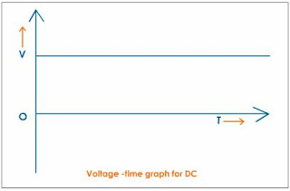
The AC(alternating current) is the current or voltage whose magnitude (generally 230V in India and 100V in US) varies with time with some frequency (generally 50Hzs in India and 60Hzs in US) , but in the case of DC the magnitude of the is constant with time (like a step function).so DC has no frequency.


DC-Voltage
we can see from the above pictures that the AC varies with time but DC is constant, moreover the DC voltage has a average value, but the average value of the AC voltage is zero for full cycle.The capacitor can store only DC voltage because average value is equal to the dc voltage,but in the case of the AC voltage,we cant store because it average value is equal to zero.
Here we are considering the case of capacitor only because all the practical batteries are nothing but capacitors which can with stand based on their voltage ranges.
# So for this reason we are interested in storing in DC voltages only
Friday, September 14, 2018
THE STORY BEHIND 15TH SEPTEMBER
THE STORY BEHIND 15TH SEPTEMBER
---NUTAN SATYA SAI RAJ .K
Every story has a hero.The hero of our story is Sir Mokshagundam Visveswaraya!!!
Every story has a hero.The hero of our story is Sir Mokshagundam Visveswaraya!!!

Sir Mokshagundam Visvesvaraya is an Eminent
Civil Engineer and Excellent Statesman. He is the oldest surviving icon from
20th Century. He was born in a poor brahmin family in Muddenahalli in 1860.He
was an engineer with a flair for bold and creative ideas. His studies and
research concentrated mainly on flow of water and building dams. He has the
credit of inventing ‘Automatic Flood Gates System’ and ‘Block Irrigation
System’ which are still considered to be marvels in engineering and they were
considered as best design in Asia in 1903.
Once
Mokshagundam Visvesvaraya, as Chief Engineer for Karnataka state visited
beautiful Sivasamudra Waterfalls, located in Karnataka over the bank of river
Kaveri. After watching them, he made a comment immediately, "What a huge
waste of Energy?”. Every one present over there was shocked by the statement.
In a flash, he got an idea to build a Hydro-electricity Project over there. His
eyes didn't see the beauty of the water falls but only saw the loss of Energy.
Hence, we can understand the dedication levels of an ideal engineer present in him!
He
also holds the credit of planning the ghat-road from Tirupati to Tirumala. The
greatest thing about that is, there was no single rock fall and accidents
occurred till today on that road. But surprisingly, some rock fall and
accidents occurred on the other road which was constructed by new generation
engineers. Visveswaraya sir planned the road in such a way that he observed
each and every corner of the mountain for few months and designed efficiently
with utmost care. Thus we can see a high level quality engineer present in him!
Have
you ever heard about floods in Hyderabad?
Surely the answer is NO. It is all because our greatest engineer
Visveswaraya Sir. In 1908 there were severe floods to Musi river in Hyderabad.
Almost 50,500 people died and many became homeless. Then he developed flood
protection system by designing and constructing the dam and drainage systems in
Hyderabad. With his engineering skills, he turned Hyderabad to flood-free city.
He also saved the Visakhapatnam port from sea erosion. The part of the port
which was constructed by him was very less affected even from the recent Hudhud
cyclone. This shows his expertise!
He
built Krishna Raja Sagar Dam which is the largest Dam in Asia at the time of
its construction. It is considered as one of the greatest achievements. At the
age of 90, Visveswaraya sir constructed a bridge over river Ganga in Bihar.
Thus we can understand level of interest present in him. He said that “Engineer
is a person who creates things which are not created by God”. These are a few
of his great works done by him. He is an engineer with a great passion!
"Work is Worship" is the motto of Sir Visveswaraya!
The
Indian government considering his greatness honoured him with Bharat Ratna in
the year 1955 and didn't find an engineer like him and therefore celebrates his
birthday 15th September as National Engineers Day every year. There are 1.3
billion Indians, 1.5 million are engineers. And yet, most of us are unaware of
the only day dedicated to this pioneering community of our country. This
article focuses a great Indian engineer Sir Mokshagundam Visveswaraya. It is
the minimum responsibility of every engineer to know about the greatness of him
and adopt the qualities of him.I consider my standards are not sufficient to
describe the greatness of Visveswaraya Sir, but I am still fortunate in trying
my level best in writing this article and I wish a very Happy Engineer’s Day in
advance to all our budding and expert innovators reforming our Nation.
"
Remember your work may be only to sweep railway crossing but it is your duty to
keep it so clean that no other crossing in the world is as clean as yours." --- Sir Mokshadundam Visveswaraya.
A video on visveswaraya sir in social media
Monday, September 3, 2018
Learn AURDINO:-
Here is the book for Beginning AURDINO.
Enjoy learning!!!!
click_here to download the book.
Saturday, August 25, 2018
TEXT BOOKS FOR ECE
BEST TEXTBOOKS FOR ECE:-
All the standard textbooks are given subject wise below. The best books preferred for each subject are given, students can see and download the book based on their understanding.
click on the respective subject name to see and download textbooks.
2.NETWORK ANALYSIS
3.DIGITAL ELECTRONICS
4.SIGNALS AND SYSTEMS
5.ANALOG ELECTRONICS
6.CONTROL SYSTEMS
7.LICA
8.MICROPROCESSORS
9.VERILOG HDL
10.ANALOG AND DIGITAL COMMUNICATIONS
11.ANTENNA THEORY AND DESIGN
12. ELECTROMAGNETICS
13.C-LANGUAGE
14.JAVA
15.QUANTUM MECHANICS
16.VLSI
17. QUANTITATIVE APTITUDE
Wednesday, August 15, 2018
Intro Mr engineer
THIS IS OUR YOUTUBE CHANNEL INTRODUCTION VIDEO STARTED BY MY FRIENDS AND ME. PLEASE STAY TUNED TO IT.https://youtu.be/gKypMW475Ew
Thursday, July 19, 2018
RFID and GPS
RFID and GPS
What is RF ID?
Radio-Frequency Identification (RFID) is the use of radio waves to read and capture information stored on a tag attached to an object without any power supply to it. A tag can be read from up to several feet away and does not need to be within direct line-of-sight of the reader to be tracked.
How does a RFID system work?
A RFID system is made up of two parts: a tag or label and a reader. RFID tags or labels are embedded with a transmitter and a receiver. The RFID component on the tags has two parts: a microchip that stores and processes information, and an antenna to receive and transmit a signal. The tag contains the specific serial number for one specific object.
To read the information encoded on a tag, a two-way radio transmitter-receiver called an interrogator or reader emits a signal to the tag using an antenna. The tag responds with the information written in its memory bank. The interrogator will then transmit the read results to an RFID computer program.
There are two types of RFID tags: passive and battery powered. A passive RFID tag will use the interrogator’s radio wave energy to relay its stored information back to the interrogator. A batter powered RFID tag is embedded with a small battery that powers the relay of information.It use rf energy harvesting techniques.
In a retail setting, RFID tags may be attached to articles of clothing. When an inventory associate uses a handheld RFID reader to scan a shelf of jeans, the associate is able to differentiate between two pairs of identical jeans based upon the information stored on the RFID tag. Each pair will have its own serial number.
With one pass of the handheld RFID reader, the associate can not only find a specific pair, but they can tell how many of each pair are on the shelf and which pairs need to be replenished. The associate can learn all of this information without having to scan each individual item.
practical usage:- in ID cards, in shopping malls on textiles, for cattle a yellow tag is placed on ears which contain the total information of animal etc.
practical usage:- in ID cards, in shopping malls on textiles, for cattle a yellow tag is placed on ears which contain the total information of animal etc.
GPS
Stands for "Global Positioning System." GPS is a satellite navigation system used to determine the ground position of an object. GPS technology was first used by the United States military in the 1960s and expanded into civilian use over the next few decades. Today, GPS receivers are included in many commercial products, such as automobiles, smartphones, exercise watches, and GIS devices.
The GPS system includes 24 satellites deployed in space about 12,000 miles (19,300 kilometers) above the earth's surface. They orbit the earth once every 12 hours at an extremely fast pace of roughly 7,000 miles per hour (11,200 kilometers per hour). The satellites are evenly spread out so that four satellites are accessible via direct line-of-sight from anywhere on the globe.
Each GPS satellite broadcasts a message that includes the satellite's current position, orbit, and exact time. A GPS receiver combines the broadcasts from multiple satellites to calculate its exact position using a process called triangulation. Three satellites are required in order to determine a receiver's location, though a connection to four satellites is ideal since it provides greater accuracy.
In order for a GPS device to work correctly, it must first establish a connection to the required number of satellites. This process can take anywhere from a few seconds to a few minutes, depending on the strength of the receiver. For example, a car's GPS unit will typically establish a GPS connection faster than the receiver in a watch or smartphone. Most GPS devices also use some type of location caching to speed up GPS detection. By memorizing its previous location, a GPS device can quickly determine what satellites will be available the next time it scans for a GPS signal.
Subscribe to:
Posts (Atom)
-
 THE STORY BEHIND 15TH SEPTEMBER --- NUTAN SATYA SAI RAJ .K Every story has a hero. The hero of our story is Sir Mokshagundam...
 -
 WHY A STEP-UP TRANSFORMER CANT BE USED AS AN AMPLIFIER? As you can see in the above figure, for a step-up transformer the amplitude o...